How to Check Quality of Cement

How You will do check the Quality of Cement when it is received at site?

Do you know, when concrete fails, one of the culprit may be the Cement.
It is important to check the Quality of Cement when it is received at site to ensure no failure and stoppage in project due to bad quality cement.

Cement is transported in the bags and bulkers.

When Cement reach at site, do check following in order to ensure the cement is of good quality or not.

Check for ISI mark on the cement bag (This tells brand is standard and follows the steps to ensure product quality and in such cases third party testing report is not required. but you may get done third party test if client demands or you want to do)

Check the Cement manufacturing details printed on side of bag for week, month and year of manufacturing.

When week 1 start and on which day in calendar?

Week 1 starts on the 1st Jan of every year.
The day on 1st date will followed as a start of week.
Say on 1st Jan, its Tuesday then week also starts on every Tuesday.

After checking the manufacturing details, do check how much old is cement.
It is advice to consume the cement within 3 months from manufacturing.
Because no one knows the conditions where cement is stocked by a supplier / trader.

Insist your company to buy cement directly from manufacturer, this ensure you get fresh cement and no alteration or damages to cement due to storage supplier / traders place.

Printing of Manufacturing week on bag happens after bag is loaded with cement on a conveyor through which bags are sent either for stacking or directly in wagon (at company no one use iron hooks)
Printing is automatically done, so sometime you may get bags on which the manufacturing details are not printed correctly (Such cases you should inform the manufacturer about this and get the written confirmation from them via email before accepting it. This will also ensure the rectification in printing process and other engineers will receive bags with clear print on bags)

Also i would like to tell you that directly order bags have not for sale or not for retail printed on it. A bag having price written on it is produced for retail sale and you might get a very old bags if you order it through retailer.

Do not accept the cement which is more than a month old (Ensure you put this point in purchase order to avoid dispute in future).

Check the weight of cement bags randomly
In India Cement industry wont care for the quality of cement, once it is dispatched from their manufacturing unit.

Cement is transported to their storage yards all over India, max through train.

On relieving cement at unload point at railway station, buggers start playing with that cement bags with iron hook. No Quality guy from that manufacturer will object this damaging of packing by those unskilled labours.
No manufacturer have power to replace those local labours at each station.

They can change the design and replace all bags instead of trying to replace labour which is impossible.

As a Engineer we all should write to all cement manufacturer to do something in order to safeguard the handling of cement.

Coming back to the point, due to improper handling and puncturing of cement bags at multiple location, there is a possibility that cement in bags wont weight exactly or above 50 Kg and people who uses standard as bag for doing their day to day work will get more failure as the bag may not be bag or 50 Kg.

So it is important to verify the bag weight is above or equal to 50 Kg to avoid failure in concrete as some one might use a bag weighting less than 50Kg as a bag and do concrete which change a whole lot mathematics and chemistry of concrete produced.

Manufacturers are aware about those losses due to handling, instead of correcting it, they had increased the quantity of cement in each bag to ensure 50Kg is delivered in normal transport loss.

After verifying the freshness on cement we can further inspect it for engineering properties.

Check the temperature of cement in bag

Sometimes you may receive a hot cement in bag, it does not mean that the hydration process is started in it.
When cement is directly loaded after manufacturing, it may be hot up to 50 degree, in such cases store cement for 2 to 3 days before using in order to allow it for cooling.

This happens when order is more than supply of cement.

If we use hot cement false set may occur in concrete produced with it.

Which means concrete will become stiff after mixing it, to regain the plasticity, remixing should be done or mixing time of such concrete need to be increased.

Check for Physical Properties

Color of The cement
It depends mostly on the color of lime stone which is used to manufacturing of the same and the other performance enhancer additives like flyash.

Cement towards off-white shade does not mean it is bad or have more flyash or any other additives (Example – AAC Cement – it have whitish lime stone, so color is slightly faint than grey shade)

Color of cement in general from shade of grey may be dark or may be faint.

You should know why it is faint or dark (Ask your company to arrange visit to manufacturer plant in order to understand manufacturing better. such visits are arrange by manufacturer free of cost on demand by the customers)

Smoothness

When you take some cement in your fingers and rubbed it, it will feel silky smooth due to fineness of cement.
If grinding is not done properly, you will feel the roughness in it.
If roughness observed, check the fineness of cement.

Lumps in bags

Lumps forms in bags due to dead weight on it called as soft lump which get breaks when we roll the bag.

Hard lumps – forms due to to hydration of cement due to moisture contact or direct contact in water during transport such as rain water entered in bag. if this is the case cement should be rejected.

Contamination

Take handful of cement and throw it in the water, it should float for sometime and then sink in water. If its directly sinking in water, it shows cement is modified after dispatch from plant and may result in failure (In such cases cubes should be casted and checked for 1 day strength, if it fails in it, cement should be rejected)

Consistency

It shows in general the water demand by cement, more it demand higher the water cement ration goes and vice a versa.

In general standard consistency ranges between 27 to 34%

Older cement may show lower water demand due to partly hydration of cement.
Also less finer cement tends to less water demand (coarser material have less surface area than finer material).

Consistency of the cement need to be tested at 27 +/- 2 degree with relative humidity of 65 +/- 5% as per IS 4031 part 4.

No need to worry if your lab is not setup with such a precision, you can still do a consistency test and record the result as per your lab temperature and verify each result with results got in previous same environment.

Compressive Strength

A good engineer always do check for the compressive strength of cement for each received batch of cement. this ensure no failure in real work.
As the lab conditions are not standard in case of most of the sites, engineer can compare his results with previous results of same cement under same condition.
Do ask to provide a standard lab set up to your company owner, this may save a huge losses at fraction of repair cost.

Cement received in bulker

Loose cement sent in bulkers do not have the manufacturing details printed on it. You need to verify it by reading the details provided on dispatch challan.
Dispatch challan do mention the seals numbers which are printed on seals fixed at bulker openings after feeding cement in it.

Before opening the seals on all opening do verify the numbers written on seal and challan are same.

After verifying it do the same process which we use for inspecting bag cement.

Preserving the sample from each lot

A Sample of cement as received should be preserve in air tight bag or container with all details about that batch. this will help in solving the dispute in future which may occur due to failure of concrete at project and also help you to blacklist the manufacturer if he does not accept the failure.

Preserve sample will give you accurate result of actual manufactured cement.

Failure in concrete may occur due to many possibilities such as

Storage condition of cement at site.
Batching condition for concrete.
Cube casting errors etc.

Don’t be afraid of Cement manufacturing companies, Mistakes may happen at plant due to carelessness of somebody (Chances are less due to advance systems and automation at plants, but human can make errors too)

Hope this will help you in checking cement, when you receive a next lot of cement at your site

Some general information on formwork:

Formwork is a temporary mould into which fresh concrete and reinforcement are placed to form a particular reinforced concrete element.

A typical breakdown of total construction percentage costs shows that formwork material and labour alone consists of 35% of the total concrete construction cost. In the construction of a structural element, the cost distribution can be found approximately as:

Concrete Cost – Materials 30%; Labour 15% = 45%

Reinforcement Steel Cost -Materials 20%; Labour 10% = 30%

Formwork Cost – Materials 15%; Labour 10% = 25%.

To ensure that the formwork is economical and practical to build, the following basic technical, economical and functional requirements that should be kept in mind when designing and constructing formwork.

Technical requirements of formwork:

Formwork should be of the desired shape, size and and fit at the location of the member in structure according to the drawings.

Formwork shall be carefully selected for required finish surface and linings to produce the desired concrete surface.

Formwork should withstand the pressure of fresh concrete and working loads and should not distort or deflect from their position during the concrete placing operation.

Formwork should support the designed loads any other applied loads during the construction period.

The formwork must not damage the concrete or themselves during removal from structure.

Panels of the formwork should be tightly connected to minimize gap at the formwork connection to prevent leakage of cement paste.

Functional requirements of formwork:

Form sections should be of the size that can be lifted and transported easily from one job site to another.

Formwork should be dismantled and moved as easily as possible so that construction of the building advances.

Formwork Units must be interchangeable so that they can be used for forming different members.

Formwork shall be designed such that it fits and fastens together with reasonable ease.

Forms should be simple to build.

Formwork should be as lightweight as possible without any strength reduction.

Forms should be made such that workers can handle them without any safety issue, respecting the Health, Safety, and Hygiene Regulation in effect.

Economic requirements of formwork:

Formwork shall be made of low cost materials, energy and labour if possible.

Formwork should be manufactured such that it can be repetitively used and shall be as adaptable as possible. They must be able to withstand a good number of reuses without losing their shape.

Formwork must be designed so that the whole formwork can be assembled and dismantled with unskilled or semi-skilled labour.

Formwork care and maintenance should be done according to specifications.

Moto X4 4gb+64gb @ Amazon for 14000 RS


Quality Control Of Construction Testing Of Concrete Cubes

The acceptance criteria of quality of concrete is laid down in IS:456-2000. The criteria is mandatory and various provisions of the code have to be complied before the quality of concrete is accepted. In all the cases, the 28-days compressive strength shall alone be the criterion for acceptance or rejection of the concrete. In order to get a relatively quicker idea of the quality of concrete, optional test for 7 days compressive strength of concrete be carried out.

6 Cubes of 150 x 150 x 150 mm size (the nominal size of aggregate does not exceed 38 mm) shall be cast, 3 for 7-days testing and 3 for 28-days testing. A set of
3 cubes (specimen) average strength will be a sample. The individual variation of a set of 3 cubes should not be more than ± 15% of the average. If more, the test result of the sample is invalid.

Note:- For aggregates larger than 38 mm, bigger than 150 mm moulds are to be used. See IS:10086-1982

CUBE MOULD:
The cube moulds of required size (150 mm for nominal size of aggregate not exceeding 38 mm) shall be made in such a manner as to facilitate their separation into two parts. Cube moulds shall be provided with a base plate and they shall be as per IS:10086-1982. The dimensions, tolerance and materials of cube moulds shall be as given in table-1.

Table-1: Dimension, tolerance and materials of 150 mm cube mould.

S.No.

Description

Requirements

1

Distance between opposite faces, mm

150 ± 0.2

2

Height of mould, mm

150 ± 0.2

3

Thickness of wall plate, mm

8

4

Angle between adjacent interior faces and between interior faces and top and bottom plates of mould.

90 ± 0.50

5

Length of base plate, mm

280

6

Width of base plate, mm

215

7

Thickness of base plate, mm

8

8

Permissible variation in the planeness of interior faces:for new moulds, mm

for moulds in use, mm

0.03

0.05

9

Permissible variation in the planeness of base plate, mm

0.03

10

materials
a) Side plate
b) Base plate

Cast iron

Cast iron

TAMPING ROD
As per IS:10086-1982, the tamping rod shall be 16±0.5 mm dia and 600±2 mm long with a rounded working end and shall be made of mild steel.

COMPRESSION TESTING MACHINE:
The compression testing machine shall be as per IS:14858-2000. The machine shall be capable of applying the load at the specified rate, uniformly without shock using manual or automatic control. The percentage of error shall not exceed ±1.0 percent of the indicated load.

On regular basis the machine should be calibrated with in a period not exceeding 12 months from previous verification. The machine is required to be calibrated on original installation or relocation, subject to major repairs or adjustment and whenever there is reason to doubt the accuracy of the results, without regard to the time interval since the last verification.

The accuracy of the testing machine shall be verified by applying five test loads in four approximately equal increaments in ascending order. The difference between any two successive loads shall not exceed one third of the difference between the maximum and minimum test loads. The load as indicated by the testing machine and the applied load computed from the readings of the verification devices shall be recorded at each test point. Calculate the error, E, and the percentage of error, EP for each point from these data as follows:
E = A – B
Ep=[E/B]x100

A = load in N indicated by the machine being verified and
B = applied load in N as determined by the calibrating device
(such as proving ring, load cell, calibrating cylinder etc.)

For checking further accuracy of testing machine concrete cubes of the same grade, batch, age in SSD condition should be tested on the machine being checked and on a already calibrated standard compression testing machine and find the difference. Proper and regular calibration of testing machines is essential.
SAMPLE OF CONCRETE
Sample of concrete for test specimen shall be taken at the mixer or in the case of ready mixed concrete from the transportation vehicle discharge. Such samples shall be obtained by repeatedly passing a scoop or pail through the discharge stream of the concrete. The samples thus obtained shall be mixed on a non-absorbent base with shovel until it is uniform in appearance.Sampling should be spread over the entire period of concreting and the frequency of sampling of concrete of each grade shall be as following:

Quantity of concrete in the work (m3)

Number of samples

1-5

1

6-15

2

16-30

3

31-50

4

51 and above

4 plus one additional sample for each additional 50 m3 or part thereof.

Note:- Frequency of sampling may be agreed upon internally by supplier and purchaser.

CASTING OF CUBES:
The cube mould plates should be removed, properly cleaned assembled and all the bolts should be fully tight. A thin layer of oil then shall be applied on all the faces of the mould. It is important that cube side faces must be parallel.

After taking concrete samples and mixing them, the cubes shall be cast as soon as possible. The concrete sample shall be filled into the cube moulds in layers approximately 5 cm deep. In placing each scoopful of concrete, the scoop shall be moved around the top edge of the mould as the concrete slides from it, in order to ensure a symmetrical distribution of the concrete with in the mould. Each layer shall be compacted either by hand or by the vibration as described below.

COMPACTION BY HAND:
Each layer of the concrete filled in the mould shall be compacted by not less than 35 strokes by tamping bar. The strokes shall be penetrate into the underlying layer and the bottom layer shall be rodded throught its depth. Where voids are left by the tamping bar the sides of the mould shall be tapped to close the voids.

COMPACTION BY VIBRATION:
When compacting by vibration each layer shall be vibrated by means of an electric or pneumatic hammer or vibrator or by means of a suitable vibrating table until the specified condition is attained.

CURING :
The casted cubes shall be stored under shed at a place free from the vibration at a temperature 220C to 330C for 24 hours covered with wet straw or gunny sacking.

The cube shall be removed from the moulds at the end of 24 hours and immersed in clean water at a temperature 240C to 300C till the 7 or 28-days age of testing. The cubes shall be tested in the saturated and surface dry condition.

For the true representation of actual strength of concrete in the structure, extra cubes shall be cast, stored and curded as per the identical conditions of that structure, and tested at required age.

TESTING OF CONCRETE CUBES:
The dimensions of the specimens to the nearest 0.2 mm and their weight shall be noted before testing. The bearing surfaces of the testing machine shall be wiped clean and any loose sand or other materials removed from the surface of the specimen which are to be in contact with the compression platens. The cube shall be placed in the machine in such a manner that the load shall be applied to opposite sides of the cubes as cast that is not to the top and bottom. The axis of the specimen shall be carefully aligned with the centre of the thrust of the spherically seated platen. No packing shall be used between the faces of the test specimen and the steel platen of the testing machine. As the spherically seated block is brought to bear on the specimen, the movable portion shall be rotated gently by hand so that uniform seating may be obtained. The load shall be applied without shock and increased continuously at a rate of approximately 140 kg/sq cm/min until the resistance of the specimen to the increasing load breaks down and no greater load can be sustained. The maximum load applied to the specimen shall then be recorded and the appearance of the concrete and any unusual features in the type of failure shall be noted, see fig-1and fig-2. The compressive strength of concrete shall be calculated from: Maximum load/Cross-Sectional area of cube To be reported to the nearest 0.5N/mm 2

ACCEPTANCE:
For the acceptance, both the conditions should be met with:
a) The mean strength determined from any group of four-non overlapping consecutive test results should comply with the appropriate limits as given in table-2

b) Any individual test result complies with in the appropriate limit as given in table-2

Table-2 : Characteristic Compressive Strength Compliance Requirement:

Specified grade

Mean of the group of 4 non-overlapping consecutive test results in N/mm2

Individual test results in N/mm2

M-15

>= fck + 0.825 x established standard deviation

(rounded off to nearest 0.5 N/mm2)

or

fck + 3 N/mm2

whichever is greater

>=fck – 3 N/mm2

M-20 or above

>= fck + 0.825 x established standard deviation

(rounded off to nearest 0.5 N/mm2)

or

fck + 4 N/mm2

whichever is greater

>= fck – 4 N/mm2

Note: In absence of established standard deviation, the values given in Table-8 of IS:456-2000 may be assumed.

INTERPRETATIONS-EXAMPLE FOR M-25 GRADE OF CONCRETE
For a pour of 31-50 m3 4 samples (each sample having 3 cubes) are mandatory.
1. The average value of set of three cubes (one sample) should have strength with in the limits of ±15% of the average value. Otherwise the result of that sample will be invalid.

2. The mean value of 4 samples (4 average values obtained from each sample of 3 cubes) should meet the criteria as given in table-2. For M-25 grade of concrete the mean value of these 4 samples should not be less than either 29 N/mm2 or 25 N/mm2 plus 0.825 times the standard deviation whichever is the greater.

3. Any individual test result of a cube out of the above should not have value less than 21 N/mm3.

In case of doubt regarding the grade of concrete used either due to poor workmanship or based on results of cube strength test further tests should be conducted such as non-destructive test by Concrete Test Hammer, Ultrasonic Concrete Tester etc. Partial destructive test by drilling cores and testing them in compression. In no case fewer than three cores be tested. The final test include the load testing on structure.

DURABILITY OF CONCRETE:
Cube testing alone is not the criteria for the durability of concrete structure. A durable concrete is one that perform satisfactorily in the working environment during its anticipated exposure conditions during service. The materials and mix proportions specified and used should be such as to maintain its integrity and if applicable, to protect embedded metal from corrosion.
It is essential that every concrete structure should continue to perform its intended functions, that is maintained its required strength and serviceability, during the specified or traditionally expected service life. It follows that concrete must be able to withstand the processes of deterioration to which it can be expected to be exposed. Such concrete is said to be durable.Both strength and durability have to be considered explicitly at the design stage. The emphasis is on the word both because it would be a mistake to replace overemphasis on strength by overemphasis on durability.

REFERENCES:

1

IS:456-2000 : Plain and Reinforced Concrete – Code of Practice. BIS, New Delhi

2

IS:10086-1982 : Specification for Moulds for use in Testing of Cement and Concrete, BIS, New Delhi

3

IS:14858-2000 : Compression Testing Machine used for testing of Concrete and Mortar Requirements, BIS, New Delhi.

4

IS:516-1959 : Method of Tests for Strength of Concrete, BIS, New Delhi.

5

kishore  kaushal : “Concrete cube testing is performance assured” Civil Engineering and Construction Review, New Delhi, January, 1990,  PP:23-24

6

kishore  kaushal : “Corrosion Damaged Concrete” Civil Engineering and Construction Review, New Delhi, January, 1991, PP:27-31

7

kishore  kaushal : “Durability and Corrosion of Steel in concrete”. The Institution of Engineers (India) All India Seminar on Durability of Concrete and Cement Products, Nagpur, 22-23 Sept, 1990

8

kishore  kaushal : “Durability of Concrete” Indian Concrete Institute Bulletin  No. 54, Jan-Mar, 1996,
PP: 11-13

9

kishore  kaushal : “Concrete Cube Testing” Civil Engineering and Construction April, 1995, PP:33

10

kishore  kaushal : “Concrete Cube Testing” Bulletin of Indian Concrete Institute No. 51, April-June, 1995

11

kishore  kaushal : “28-days Strength of Concrete in 15 Minutes” Civil Engineering and Construction, August, 1992, PP: 38-41

12

kishore  kaushal : “Non-Destructive Testing of Concrete” Builders Friend, Lucknow, Feb, 1992, PP: 3-4


Wrong Myths On Column Construction – A Challenge To Overcome


By
Sourav Dutta
Manager-Civil

Introduction
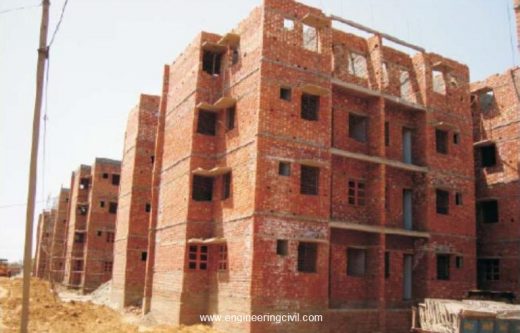
There are a number of ways in which the superstructure can be built. In areas where average to good quality bricks are available, the walls of houses for two to three storeyed constructions can be built out of bricks with the slabs, lintels, chajja etc. in reinforced concrete. Such construction is termed as load bearing construction (Fig 1). This is essentially because the entire load coming from the slabs, beams, walls etc is transmitted to the foundation through the brick walls.

fig-1-brick-load-bearing-construction
Fig 1: Brick Load Bearing Construction

With natural hazards like earthquake or high speed storms hitting various parts of country more frequently, such load bearing wall construction is no longer safe for withstanding horizontal drifts unless retrofitted. Also such construction is suitable upto G+2 storied building in general.

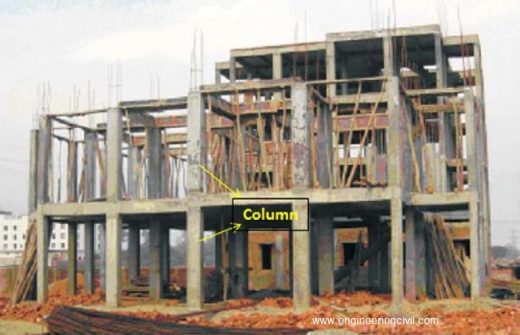
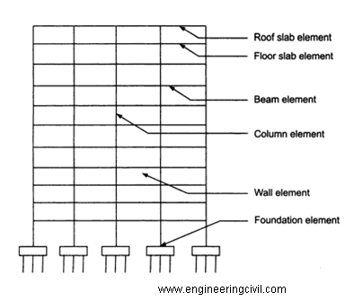
Also as the need of building high storied construction increases, coupled with natural hazards, it is advisable to opt for RCC (Reinforced Cement Concrete) framed construction (Fig 2). Basically, RCC framed construction consists of a series of columns provided suitably in the house which are interconnected by beams to form a frame. These columns transfer the building load to underneath soil through RCC footings.

The frame, starting from the foundation, has to be designed by a structural engineer who would decide upon the mix of concrete to be used, the sizes of columns and beams as well as the reinforcement to be provided therein, depending on the loads to be sustained by the structure.

Advertisements one plus 6 @ amazon.in only for 34999 INR

What is Column?

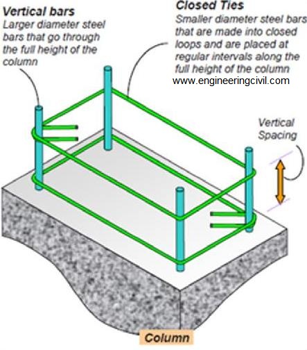
Column is a vertical compression member which transmits load of the structure to foundations (Fig 2). They are reinforced by means of main longitudinal (vertical) bars to resist compression and/or bending; and transverse steel (closed ties) to resist shearing force (Fig 3).

Typical Loads to be considered for Column Design
(i) Dead Load: Any permanent load acting on the column, e.g. self-weight of column, weight of beam

(ii) Live Load: Any non-permanent or moving load

(iii) Earthquake Load: Depends on the seismic zone where building is located. Higher is the zone, more is the load

(iv) Wind Load: Depends upon the wind speed, height & location of building. Also terrain and adjacent structures play a role in determination of this load

fig-2-transmits-load-of-the-structure-to-foundations
Fig 2

fig-3-resist-shearing-force
Fig 3

Column Construction: Busting Myth

S No Myth Actual
1 4-12 or   4-16 dia may be sufficient for my building of 2/3 storey Column is the most important structural member to transfer the floor loads coming from each floor. Failure of column can lead to bulging or collapse   of whole structure. Depending on plan   layout of your building, loads coming and nos of storey, column cross-section and its rebar are determined. There is no standard guideline as such.
2 25mm (1 inch) clear cover is sufficient for columns Clear cover   is provided based   on durability (exposure) and fire resistance criteria. As per BIS456-2000(b), it is recommended to use min 40 mm cover (approx. 1.5 inch) for columns. However if column section is less than 200 mm and rebar dia 12 mm, then only 25 mm (1 inch) clear cover is possible.
3 6 mm rings/ties are too thin to hold the column rebars Use of 6 mm rings is allowed as per BIS guidelines and makes no difference to the structural stability of column, provided it is made and fixed as per BIS guidelines. It also results in significant savings over 8 mm rings.
4 Rings can be placed at a standard spacing   (150/200 mm   c/c) throughout in thecolumn As per the guidelines of ductile design code for RCC structures BIS 13920, rings should be placed at closer distance (about 3’’ to 4’’) upto L/6 distance [L=unsupported height of column] from any beam- column joint. The spacing in the balance central part of column can be 6’’.
5 8   mm or 10 mm rebar as vertical bars of column can be sufficient It is recommended in BIS456-2000(b) to   use min 12mm   rebar as column verticals, irrespective of any condition. However, the number of rebar would be decided based on design engineering.

Recommended construction practices for columns
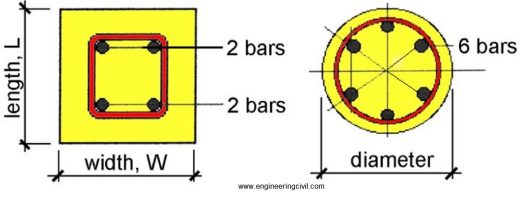
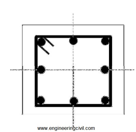
1. A minimum of 4 longitudinal rebars in rectangular and 6 in circular columns should be provided in a column (Fig 4).

2. Rebars should be placed symmetrically across the axes of symmetry (Fig 5). With unsymmetrical reinforcement there is always a danger of smaller amount of steel being wrongly placed on the face requiring the larger reinforcement.

fig-4-four-longitudinal-rebars-in-rectangular
Fig 4

fig-5-rebars-should-be-placed-symmetrically-across-the-axes-of-symmetry
Fig 5

3. If column rebar is to be used for future construction or expansion, it is recommended to apply a coat of cement slurry (cement: water = 1: 3) to the exposed portion of rebars and wrap them with some polythene or jute cloth to prevent direct contact with atmosphere to guard against atmospheric corrosion and therefore loss of material for joining for future constructions.

Note: Cement slurry provides a natural guard against the atmospheric corrosion to protect it.

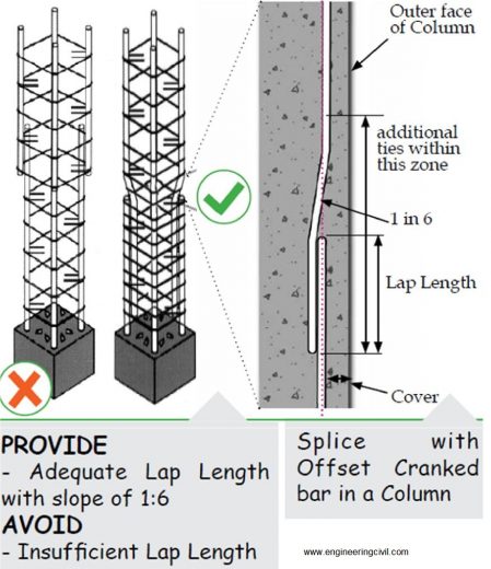
4. While lapping/splices column rebars, it should be ensured that the connecting rebar is given a slope of 1 in 6 (minimum) such that the centre line of both rebar coincides (Fig 6).

fig-6-centre-line-of-both-rebar-coincides
Fig 6

fig-7a
Fig 7(a)

fig-7b-failure-of-column
Fig 7(b)

5. Lapping should preferably be done in the centre part of column with a min lap length of 57 times the dia of rebar(c). So if you are using 16 mm rebars then lap length will be 3 feet.

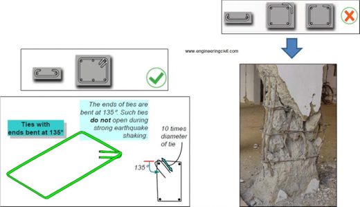
6. The ends of the ties must be bent as 135° hooks. The length of tie beyond the 135° bends must be at least 10 times diameter of steel bar used to make the closed tie; this extension beyond the bend should not be less than 75 mm (Fig 7a).

If this guideline is not followed then the tie/ring holding the vertical rebars have a higher probability of opening up during an event like earthquake. This consequently may lead to failure of column (Fig 7b).

7. Minimum grade of concrete to be used for building a RCC column is M20.

8. Minimum percentage of steel to be used in a RCC column is 0.8% of cross-sectional area of column.

Note on Honeycombing
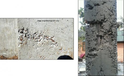
Honeycombs are hollow spaces and cavities left in concrete mass on surface or inside the concrete mass where concrete could not reach. These look like honey bees nest (Fig 8).

Honeycombs which are on sides are visible to naked eyes and can be detected easily as soon shuttering is removed. Honey combs which are inside mass of concrete can only be detected by advanced techniques like ultrasonic pulse velocity testing or rebound hammer test.

Honeycomb is formed mainly due to:
a) Improper vibration/compaction

b) Less cover to reinforcement bars

c) Construction joints (joints upto which a stage of construction is done) are the typical positions where honeycombs are observed. This is due to non-treatment of construction joints (cleaning of laitance and loose cement slurry from joint using wire brush/chipping) before resuming construction.

d) Improper mix proportioning of various components of concrete and/or improper gradation of aggregates are also responsible for such honeycomb formation.

Remedies for Honeycombs in Concrete:
• Strictly speaking wherever honeycombs are observed concrete should be chipped off at that location and the portion should be re-built after applying fresh concrete. Honeycombs as a defect not only reduces the load bearing capacity but water finds an easy way to reinforcement rods and corrosion starts. Corrosion is a process which continues through reinforcement rods even in good concrete, which results in loosing grip between rods and concrete, which is very dangerous to safety and life of concrete structures.

• It will not be out of context to point out that by applying superficial cement plaster on the honeycombs can be a temporary solution of hiding them, but is never safe/advisable.

• At beam-column junction, concrete with 20 mm and below graded aggregates can be used with slightly more water and cement to avoid honeycombs.

• Use of needle vibrator for proper compaction of concrete helps in reducing honey combs. The fresh concrete should be thoroughly vibrated near construction joints so that the mortar from new concrete flows between large aggregates and develops proper bonding with old concrete.

Advertisements  one plus 6 @ amazon.in only for 34999 INR

References
(a) BIS 1786 is the BIS code which gives the guidelines pertaining to steel quality for all steel manufacturers to follow
(b) BIS 456-2000 is the BIS code of practice for plain and reinforced concrete structures
(c) Suggestion made considering M20 grade of concrete (cement:sand:graded stonechips=1:1.5:3) and Fe500 grade of HYSD rebar

Proper Slab Construction Concepts – A Challenge to overcome

By
Sourav Dutta
Manager-Civil

What is slab?
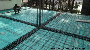
A RCC (Reinforced Cement Concrete) slab is the most common structural element of any type of building. Horizontal slabs, typically between 4 and 20 inches (100 and 500 millimeters) thick, are most often used to construct floors and ceilings.Here discussion on “flat slab” has not been considered.

proper-slab-construction-concepts

proper-slab-construction-concepts2

Typical loads to be considered for slab design
(i) Dead load: Any permanent load acting on the slab e.g. self-weight of slab, weight of floor finish & plaster

(ii) Live Load: Any non-permanent or moving load e.g. weight of occupants, furniture, and partitionon the slab

(iii) Snow load (if any)

Note: Earthquake and Wind loads are not considered in the design of slabs.

Slab construction: Busting myth

S. No. Myth Actual
1


Slab design would change based onearthquake zoneof the location where my building will be constructed. Thus in more earthquake prone zones, more rebar should be used in slab. Slab design will always be similar anywhere in India because it has no relation to the earthquake zone of location where your building will be constructed.
2 More rebar in slab would make it more strong and durable. Placing more rebar/less spacing than required leads to higher crack width formation in slab because the higher weight of rebar would lead to higher deflection.
3 Minimum 8mmdia rebar is required for slab construction. However, it is better if 10mm or 12mm diarebar can be used with spacing of 100-125mm (4-5’’) between rebar. For general residential construction, 8mm rebar placed @ 150 mm (6’’) apart (centre-to-centre) is sufficient as main rebar and binders(a). [Even 6 mm rebar placed @ 150 mm (6’’) centre-to-centre is sufficient as binders(a)]
4 100 mm slab depth is sufficient for residential construction which is alsovalid for any size of slab panel. 100 mm (4 inches) slab depth is sufficient for up to 12ft x 12ft maximum slab panel size(b). Slab depth needs to be increased to control deflection, if slab panel size(b) increases. Other than that, roof slab depth can be increased for better comfort during summer season, without changing the no of rebars for slab (refer topoint 3).
5 If size of slab panel increases, increase rebardia to 10mm and 8mm, without changing slab depth. The depth of slab needs to be increased if slab panel size(b) increases, but rebar requirement remains the same for slab (refer to point 3).
6 20mm clear cover in slab is sufficient. 20mm clear cover is sufficient for intermediate floor slabs, and 30mm clear cover should be provided for roof slab exposed to rain(c).
7 The rebar used in the slab have resulted in the formation of cracks. There is no known influence of quality of rebar on the development of cracks in slabs, unless the rebar is of too inferior strength than required. Factors such as: Building design not factoring the safe bearing capacity of soil, differential settlement of footings and wrong design engineering, poor construction practices (such as improper concrete mix proportioning, higher water-cement ratio, improper compaction, inadequate curing, improper construction joint treatment) are in general responsible for the development of cracks in the slabs.

Recommended slab construction practices:
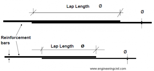
1. For lapping/ joining of rebar, a minimum lap length of 57 x diameter of rebar should be provided(a). Thus 1.5ft lap length will be required if you are using 8mm diarebar. Lapping should preferably be avoided at centre of slab panel.

Advertisements

Note: Lapping refers to the joining of rebars to achieve the desired continuity.

lapping-joining-of-rebar

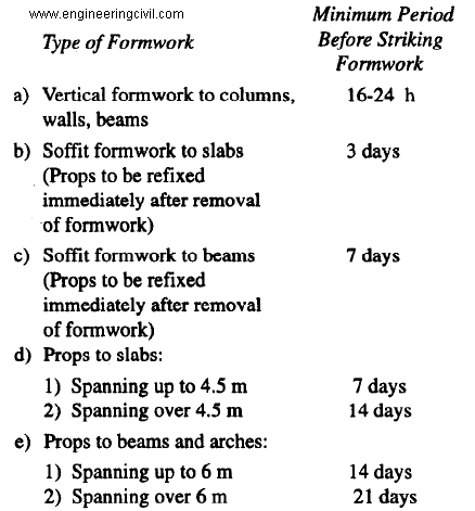
2. The guidelines of minimum period before striking/removal of soffit shutter and vertical props of slab and beam as per BIS are as follows:

the-guidelines-of-minimum-period-before-striking

3. Slab curing should be done for minimum of 14 days from date of casting, as per BIS. It is recommended to do curing for a period of 28 days.

4. During waterproofing treatment of roof slab, mix standard waterproofing compound with concrete and apply on slab in ½’’ to 1’’ layer in single pour without any time lag between laying the mix (with supporting props in position). This is to avoid any construction joint in the waterproofing layer. (This layer to be poured in a bit slope to ensure proper drainage)

5. To accelerate setting of concrete in heavy rainfall/snowfall prone areas, standard accelerating admixture complying with BIS9103 may be used.

NOTE:
(a) Design is suggested considering M20 grade of concrete (cement:sand:stonechips=1:1.5:3)and Fe500(D) grade of HYSD rebar

(b) Slab panel size means the centre-to-centre dimensions of the space enclosed by beams

(c) For slab exposed to severe rainfall, BIS recommends 45mm clear cover.

Mix design M25 Grade designed as per IS 10262:2009 & IS 456:2000

Mix proportioning for a concrete of M25 grade is given in A·I to A-ll.

A·I STIPULATIONS FOR PROPORTIONING

a) Grade designation : M25
b) Type of cement : OPC 53 Grade conforming IS 12269
c) Maximum nominal size of aggregate : 20mm
d) Minimum cement content : 300 kg/m3 (IS 456:2000)
e) Maximum water-cement ratio : 0.50 (Table 5 of IS 456:2000)
f) Workability : 100-120mm slump
g) Exposure condition : Moderate (For Reinforced Concrete)
h) Method of concrete placing : Pumping
j) Degree of supervision : Good
k) Type of aggregate : Crushed Angular Aggregates
m) Maximum cement content : 340 kg/m3
n) Chemical admixture type : Super Plasticizer ECMAS HP 890

A-2 TEST DATA FOR MATERIALS
a) Cement used : OPC 53 Grade conforming IS 12269

b) Specific gravity of cement : 3.15

c) Chemical admixture : Super Plasticizer conforming to IS 9103 (ECMAS HP 890)

d) Specific gravity of

1) Coarse aggregate 20mm : 2.67
2) Fine aggregate : 2.65
3) GGBS : 2.84 (JSW)

e) Water absorption:

1) Coarse aggregate : 0.5 %
2) Fine aggregate (M.sand) : 2.5 %

f) Free (surface) moisture:

1) Coarse aggregate : Nil (Absorbed Moisture also Nil)
2) Fine aggregate : Nil

g) Sieve analysis:

1) Coarse aggregate: Conforming to all in aggregates of Table 2 of IS 383
2) Fine aggregate : Conforming to Grading Zone II of Table 4 of IS 383

A-3 TARGET STRENGTH FOR MIX PROPORTIONING
f’ck =fck + 1.65 s
where
f’ck = target average compressive strength at 28 days,
fck = characteristics compressive strength at 28 days, and
s = standard deviation.

From Table I of IS 10262:2009, Standard Deviation, s = 4 N/mm2. Therefore, target strength = 25 + 1.65 x 4 = 31.6 N/mm2.

A-4 SELECTION OF WATER•CEMENT RATIO
Adopted maximum water-cement ratio = 0.47.

From the Table 5 of IS 456 for Very severe Exposure maximum Water Cement Ratio is 0.50
0.47 < 0.50Hence ok. A-5 SELECTION OF WATER CONTENT
From Table 2 of IS 10262:2009, maximum water content for 20 mm aggregate = 186 litre (for 25 to 50 mm slump range) Estimated water content for 100 mm slump = 186+ (6/186) = 197 litre.

(Note: If Super plasticizer is used, the water content can be reduced upto 20% and above.)

Based on trials with Super plasticizer water content reduction of 20% has been achieved, Hence the arrived water content = 197-[197 x (20/100)] = 158 litre.

A-6 CALCULATION OF CEMENT CONTENT
Adopted w/c Ratio = 0.47
Cement Content = 158/0.47 = 336 kg/m3
From Table 5 of IS 456, Minimum cement content for ‘Very severe’ exposure conditions 300kg/m3

336 kg/m3 > 300 kg/m3 hence ok.

A-7 PROPORTION OF VOLUME OF COARSE AGGREGATE AND FINE AGGREGATE CONTENT
From Table 3 of (IS 10262:2009) Volume of coarse aggregate corresponding to 20 mm size aggregate and fine aggregate (Zone II) for water-cement ratio of 0.50 =0.62 .

In the present case water-cement ratio is 0.44. Therefore, volume of coarse aggregate is required to be increased to decrease the fine aggregate content. As the water-cement ratio is lower by 0.06. The proportion of volume of coarse aggregate is increased by 0.02 (at the rate of -/+ 0.01 for every ± 0.05 change in water-cement ratio).

Therefore, corrected proportion of volume of coarse aggregate for the water-cement ratio of 0.47 = 0.63

NOTE – In case the coarse aggregate is not angular one, then also volume of coarse aggregate may be required to be increased suitably based on experience & Site conditions.

For pumpable concrete these values should be reduced up to 10%. Therefore, volume of coarse aggregate =0.63 x 0.9 =0.57.

Volume of fine aggregate content = 1 – 0.57= 0.43.

A-8 MIX CALCULATIONS
The mix calculations per unit volume of concrete shall be as follows:
a) Volume of concrete = 1 m3

b) Volume of cement = [Mass of cement] / {[Specific Gravity of Cement] x 1000}
= 336/{3.15 x 1000}
= 0.106 m3

c) Volume of water = [Mass of water] / {[Specific Gravity of water] x 1000}
= 158/{1 x 1000}
= 0.158m3

d) Volume of chemical admixture = 1.75 litres/ m3 (By Trial and Error Method used 0.4% by the weight cement)

e) Volume of all in aggregate = [a-(b+c+d)]
= [1-(0.106+0.158+0.004)]
= 0.732 m3

f) Mass of coarse aggregate= e x Volume of Coarse Aggregate x Specific Gravity of Fine Aggregate x 1000
= 0.732x 0.57 x 2.67 x 1000
= 1114 kg/m3

g) Mass of fine aggregate= e x Volume of Fine Aggregate x Specific Gravity of Fine Aggregate x 1000
= 0.732 x 0.43 x 2.65 x 1000
= 834 kg/m3

A-9 MIX PROPORTIONS
Cement = 269kg/m3
GGBS = 67 kg/m3 (20% By Total weight of Cement)
Water = 158 l/m3
Fine aggregate = 834 kg/m3
Coarse aggregate 20mm = 891 kg/m3
12mm = 223 kg/m3 (20% By Total weight of Coarse Aggregate)
Chemical admixture = 1.34 kg/m3 (0.4% by the weight of cement)
Density of concrete = 2443 kg/m3
Water-cement ratio = 0.47
Mix Proportion By weight = 1: 2.48: 3.31

NOTE – Aggregates should be used in saturated surface dry condition. If otherwise, when computing the requirement of mixing water, allowance shall be made for the free (surface) moisture contributed by the fine and coarse aggregates. On the other hand, if the aggregates are dry the amount of mixing water should be increased by an amount equal to the moisture likely to be absorbed by the aggregates. Necessary adjustments are also required to be made In mass of aggregates. The surface water and percent water absorption of aggregates shall be determined according to IS 2386

A-10 The slump shall he measured and the water content and dosage of admixture shall be adjusted for achieving the required s lump based on trial , if required. The mix proportions shall he reworked for the actual water content and checked for durability requirements.

A-11 Two more trials having variation of ± 10 percent of water-cement ratio in A-10 shall be carried out and a graph between three water-cement ratios and their corresponding strengths shall he plotted to work out the mix proportions for the given target strength for field trials. However, durability requirement shall be met.

Realme 1 4+64 gb at Amazon

How to check quality of Bricks on site

Bricks are building blocks of a structure. Brick is most extensively used materials of the building construction.

As an engineer, you must know how to check the quality of bricks on site. A good quality of brick should be chemically inert that means it won’t show any reaction when it mixed with any material.

In this post, I am making you learn how to check the quality of bricks on site

How to select the right variety/ quality of brick in your construction:-
/ Characteristics of a good quality brick:-

How to check the quality of bricks on site:-

To chose the right quality of brick one should test the brick for following tests:-

1. Uniform Color, Size, and Shape:

A good quality of bricks should be well burnt and have a color of rich red or Copper color, any other color other than above resembles that brick is under burnt or over-burnt. If bricks are over or under-burnt, then it loses it shape.

Brick should be uniform in size it shouldn’t have any bulks on edges.
More the bulking in brick needs more mortar. It ultimately increases the cost of a building. A good brick should be sharp at edges.

A good quality of bricks should have an accurate dimension whereas +/- 3 tolerance is allowed.


Accurate dimension to check quality of bricks on site

2. Hardness test:-

Scratch the brick using your fingernails. A good brick should not show any impression of a fingernail on the brick.

Throw the brick at the height of 1.5m to the ground. A good quality brick won’t break when it is fallen from the 1.5m height,

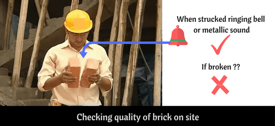
Take two bricks one in each hand and stuck it each other a good brick hears a metallic sound or ringing sound. If brick breaks without sound then it isn’t suitable for construction.

Hardness test to check quality of bricks on site

Check for Homogeneity:-

Break the brick and examine it. A good quality brick should be homogeneous, compact and with zero lumps.

Water absorption test of brick:-

A good brick should absorb less than 20% of water when it is immersed in water for 24hrs. If the brick absorbs more than the allowable limit. It absorbs water from cement mortar during its bonding. This eventually affects the brick bonding strength,

To test the water absorption follow the below procedure:
take a brick and weight it as (W1)

Now immerse the brick in water for 24 hrs. and then weight it as (W2)

Find out the percentage increase of brick weight by adopting below formula

Water absorption in the brick formula:

water absorption of brick formula

Check for efflorescence on bricks:-

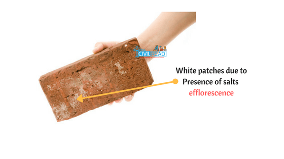
Efflorescence is a salt deposit seen on the surface of bricks. Usually, it’s in white. This can be visually inspected by checking white patches on the bricks surface, White patches on bricks resemble presence of sodium and potassium salts on it which is not suitable for construction.

Soils used in the manufacturing of bricks should free from sulphate, potassium and sodium. If brick contains such harmful salts then will get dissolved when bricks come into contact with water.

When bricks contain such harmful salts as used exposed surface then serious surface disruption occur which may harm outer plastering. This phenomenon is called efflorescence.

efflorescence in bricks

As per IS 3495 – 1992. To check the presence of efflorescence following procedure is adopted

efflorescence in bricks

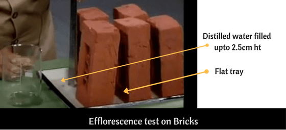
  1. Take a flat tray and fill it with a 2.5cm height of distilled water.
  2. Treat five bricks as a test specimen and place these bricks vertically one after other. On a tray containing distilled water.  Now wait until the water is absorbed by bricks
  3. Again fill the water up to same height 2.5cm and allow it to absorb water as above (Second evaporation)
  4. Now after second evaporation, examine the brick for efflorescence as below:
Description Extent of Deposits
Nil No perceptible deposit of efflorescence
Straight 10% area covered with a thin salts deposits.
Moderate Upto 50% area covered by heavy deposit.
No powdering or flaking
Heavy 50% or more area covered.
No powdering or flaking.
Serious Heavy Deposit
Powdering or flaking is observed

Brick is only used if the extent of efflorescence is from slight to moderate. The above-mentioned tests are the simple and reliable test which gives an idea about the quality of bricks on site.

WHAT SHOULD BE THE SPACING OF REINFORCEMENT AMONG VARIOUS REINFORCED CONCRETE MEMBERS

Lowest Spacing Among Bars in Tension: The least horizontal spacing among two parallel main bars will be determined as follow :-

The diameter of bigger bar or maximum size of coarse aggregate + 5 mm.

In case, the compaction is performed with needle vibrator, the spacing may be again decreased to two-third of the nominal maximum size of the coarse aggregate.

The least vertical distance among two main bars should be as follow :-
(a) 15 mm,
(b) two-third of the nominal size of coarse aggregate, or
(c) maximum size of the bar or whichever is higher.

Highest Spacing among Bars in Tension

Usually these spacing are as follow :

(a) For beams, the gapping should be 300 mm, 180 mm and 150 mm for grades of main reinforcement of Fe 250, Fe 415 and Fe 500, correspondingly.
(b) For slabs

(i) the highest spacing among two parallel main reinforcing bars should be 3d or 300 mm or whichever is less, and
(ii) the highest spacing among two secondary parallel bars should be 5d or 450 mm or whichever is less.

Reinforcement Requirement in Members:

Beams:

(a) Least tensile steel is presented with the ratio What should be the Spacing of Reinforcement among various reinforced concrete members (For Flanged Beams b= bw)
(b) Highest Tensile Reinforcement in Beams should be under 0.04 bD.
This reinforcement should be uniformly allocated on two faces at a gapping not surpassing 300 or web thickness or whichever is less.
(c) Highest area of compression reinforcement should be under 0.04 bD.
(d) Beam with depth over 750 mm, side face reinforcement of 0.1% of web area should be arranged.


Samsung J6 infinity at amazon:


BASIC THINGS YOU SHOULD KNOW ABOUT BILL OF QUANTITY (BOQ)

BILLS OF QUANTITIES (BOQ)

The survival of any business is heavily depend on the success of commercial management. When it comes to commercial management in construction industry, Bill of Quantities (BOQ) is the term which brings attention of every construction professionals and stakeholders.

It is one of the communication tool which connects the parties (Client, consultant & contractor) of construction project. Keith defines, BOQ is a schedule which categories, details and quantifies the materials and other cost items to be used in construction project. It is important to know that, direct costs & indirect costs are to be considered for complete cost of the project which are covered in different parts of the BOQ.

Generally BOQ is in tabular form which contents description, unit, quantity, rate & amount in different columns.

Sample BOQ Document, PDF

Description column provides a brief explanation of what to be done. For example, in the first item, the 32mm diameter CPVC pipes should be laid for cold water services in 20 bar operating pressure. Specification & drawings are other two important items to be analyzed in detail for clear understanding. Here the term engineer means the consultant for the project.

THE IMPORTANCE OF BOQ

BOQ shall be used in every phase (pre-contract & post-contract) of the project but need of BOQ differs based on different contract agreements & project. The major usages are listed below.

  1. It provides basic idea of the project by giving the quantities to tenderers.
  2. It defines the extent of the work. (But it should be identified in line with drawings & specification as well).
  3. It gives estimated or anticipated contract sum. (very important to client)
  4. It provides a basis for valuation of variation. (Variation is to be discussed in detail).

THE MAJOR PARTS OF BOQ

Parts of BOQ can be varied according to the project size as well the practices. Generally it has measured works, Preliminaries & Provisional sums. The contract sum would be addition of these three items.

PRELIMINARIES

In construction industry, preliminaries is known as the indirect cost for execution of project but these are the costs which is very much vital for the construction activities. The reason for these cost mentioned separately is it is very difficult to distribute these cost amongst with measured works. The examples for preliminaries listed below.

  1. Charges for performance bond, advance payment guarantee & Workmen compensation
  2. Maintenance of the site clean
  3. Requirement of site office, site stores & staff accommodation.
  4. Cost towards the project management staff (QS, Project Manager, Engineering professionals)
  5. Charges for drawings & safety

From the above mentioned examples, it can be understood these costs cannot be distributed to work item but without these expenses there will be no project.

MEASURED WORKS

It is the actual or estimated work will be carried out to complete the project. The works have been measured in different units. They are liner meter, square meter, cubic meter, number, item & etc. Value of measured works will be calculated by multiplication of quantities and rate.

PROVISIONAL SUMS

It is the sum which is allocated for the undersigned works at the tender time. It will be adjusted after the execution of the project.

In summary BOQ is very much important for the commercial management purposes. It should be understood by every construction professional to deliver a quality and expected product to client. In other words to provide value for money.

Important Guidelines for Column Shuttering

 In this article I will discuss some useful guidelines for column shuttering, Many students they don’t know column shuttering guidelines during fixing of it.

Important Guidelines for Column Shuttering

1: Before fixing shutting for column we have to apply oil or grease in the inner surface of plywood sheet or steel sheet.

2: Column shuttering should be properly aligned vertical with 90 degree to the earth.

3: If we apply oil on inner surface of column shutting its can remove very easily after closing work.
4: Plywood joints should be sealed with plaster otherwise it can be leakage.

5: Concrete should be filling the fomwork vertically during concreting.

6: After fishing concrete work, the formwork ( shuttering) should be not damage.

7: internal size of concrete column should be keep with clear dimension.

8: The column shuttering should be remove after 24 hrs.